
schematic diadram of gold processing plant manufacturer Grasping strong production capability, advanced research strength and excellent service, Shanghai schematic diadram of gold processing plant supplier create the value and bring values to all of customers.
 WhatsApp)
Briggs and Stratton Illustrated Parts Diagrams available online from LawnMowerPros and ready to assist you in finding your repair parts. We are an Authorized Briggs and Stratton Small Engine Dealer carrying a large selection of Illustrated Parts Lists.
This is a schematic process flow diagram of the processes used in a typical oil refinery. This process flow diagram (PFD) example was redesigned from the Wikimedia Commons file: ... "An oil refinery or petroleum refinery is an industrial process plant where crude oil is processed and refined into more useful products such as ...
Jul 15, 2020· Making process diagrams and attractive too can be a mind boggling step. In this tutorial ill help the beginners in learning process and thinking ideas how to make their very first sketched ...
Flowchart Maker and Online Diagram Software. (formerly ) is free online diagram software. You can use it as a flowchart maker, network diagram software, to create UML online, as an ER diagram tool, to design database schema, to build BPMN online, as a circuit diagram maker, and more. can import .vsdx, Gliffy™ and Lucidchart™ files .
The image below is a schematic block flow diagram of a typical natural gas processing plant. It shows various unit processes converting raw natural gas into gas pipelined to end users. The block flow diagram also shows how processing of the raw natural gas yields byproduct sulfur, byproduct ethane, and natural gas liquids (NGL) propane, butanes and natural gasoline (denoted as pentanes +).
The gold cyanide complex is then extracted from the pulp or slurry by adsorption onto activated carbon. CIL stands for carboninleach. This is a gold extraction process called cyanidation where carbon is added to the leach tanks (or reaction vessel) so that leaching and adsorption take place in .
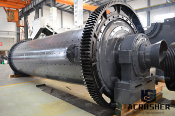
Ball Mill Process Diagram. Dry grinding ball mill process flow diagram products 1 8 of 8 ball mill plant for minerals flow chart bing diagram for ball mill gold process rod mills are less common than ball mills for grinding minerals get more info image the fl ball mill is designed for grinding of clinker gypsum and dry or moist additives to any ...
Gold Processing Plant 911Metallurgist. The Gold Processing Plant control station includes the water distribution manifold. The large barb on the left hand side is the clean water connection. Connect this to a pump capable of supplying both the clean process water near 15 L/M and the slurry water near 77 L/m (to make 30% solids at 2 tph) at 15 ...
schematic diagram of crushing plant for road project. schematic diagram of crushing plant for road project For each project scheme design, we will use professional knowledge to help you, carefully listen to your demands, respect your opinions, and use our professional teams and exert our greatest efforts to create a more suitable project scheme for you and realize the project investment value ...
Lihir processing plant is designed to process Mtpa of ore containing % sulphide sulphur at a gold grade of up to 13 g/t and a plant availability of 86%. The instantaneous design feed rate is 375 t/h of ore containing 27 t of sulphide sulphur.
Browse process flow diagram templates and examples you can make with SmartDraw.
schematic diagram of coal mine. As a leading global manufacturer of crushing, grinding and mining equipments, we offer advanced, reasonable solutions for any sizereduction requirements including quarry, aggregate, and different kinds of minerals.
Gold ore . Prominer maintains a team of senior gold processing engineers with expertise and global experience. These gold professionals are specifically in gold processing through various beneficiation technologies, for gold ore of different characteristics, such as flotation, cyanide leaching, gravity separation, etc., to achieve the processing plant of optimal and costefficient process designs.
Process Flow Diagram Of Gold Plant Process overview and description The CIP process A blockflow diagram of a typical CIP plant for a nonrefractory gold ore is shown in Figure 2. Table I and Table II illustrate the capital and operating cost breakdowns for a typical South African gold plant.
work in order to optimize the leaching process. A gold leaching model, based on the wellknown shrinkingcore model, is presented in this work. ... Figure 2 Schematic representation of the local corrosion cell at a gold surface ... Figure 25 Schematic diagram of a carboninpulp or carboninleach process with three tanks, showing interstage ...
This is a Diamond Processing Chart as it was done in the 1950s. World demand and production of diamond both for gem and industrial purposes has increased nearly fivefold during the past 25 years. Improved mining and recovery methods together with the discovery and development of new fields has enabled mining operations to fill the growing demands. Producing areas in Canada, South Africa ...
currently operating plant. Process overview and description The CIP process A blockflow diagram of a typical CIP plant for a nonrefractory gold ore is shown in Figure 2. Table I and Table II illustrate the capital and operating cost breakdowns for a typical South African gold plant. These figures are not a standard but reflect the nature of ...
Gravity Gold Recovery Process Description And Diagrams. By utilizing gravity ahead of the leach train early recovery of gold in the process can have financial benefits and avoid potential losses gravity recovery is also a useful diagnostic tool and has been used to check for the potential salting of samples removal of coarse gravityrecoverable gold can also enhance leach kinetics in plant practice
The lifecycle of a gold mine. People in hard hats working underground is what often comes to mind when thinking about how gold is mined. Yet mining the ore is just one stage in a long and complex gold mining process. Long before any gold can be extracted, significant exploration and development needs to take place, both to determine, as accurately as possible, the size of the deposit as well ...
Basics 6 kV 3Line Diagram : Basics 7 kV 3Line Diagram : Basics 8 AOV Elementary Block Diagram : Basics 9 kV Pump Schematic : Basics 10 480 V Pump Schematic : Basics 11 MOV Schematic (with Block included) Basics 12 12/208 VAC Panel Diagram : Basics 13 Valve Limit Switch Legend : Basics 14 AOV Schematic (with Block included)
Free editor to create online diagrams. Use our diagram editor to make Flowcharts, UML diagrams, ER diagrams, Network Diagrams, Mockups, floorplans and many more. Open and save your projects and export to Image or PDF.
A process flow diagram (PFD) is a diagram commonly used in chemical and process engineering to indicate the general flow of plant processes and equipment. The PFD displays the relationship between major equipment of a plant facility and does not show minor details such as piping details and designations. Another commonly used term for a PFD is a flowsheet
barite powder processing plant process flow diagram. barite powder processing plant process flow diagram For each project scheme design, we will use professional knowledge to help you, carefully listen to your demands, respect your opinions, and use our professional teams and exert our greatest efforts to create a more suitable project scheme for you and realize the project investment value ...
Schematic Diagram Of Iron Ore ilcapricciofalisolle. manufacturing iron ore diagrams . schematic diagram of iron ore to steel. iron ore processing schematic diagram YouTube. Aug 14 2016 This is a simple video slideshow if you want to know more details please click on our website schematic diagram for manufacturing iron ore .
WhatsApp)