
fly ash handling flow diagram manufacturer Grasping strong production capability, advanced research strength and excellent service, Shanghai fly ash handling flow diagram supplier create the value and bring values to all of customers.
 WhatsApp)
INTEGRATED FLY ASH HANDLING SYSTEM: (Schematic flow diagram) Stage I C stn. Fly ash Hoppers Exist. Recip Compr Compr. Fine Ash. 30 TPH. C 1 Existing Silo (Cap:350 T) Silo (New) 130 ( ''C'' stn) F stn. Intm. Hopper. F stn. Fly ash Hoppers (After rehibilitation) Stage II CentrifugalCo mpr. StageII 80 TPH. 80 TPH. Stage I Centrifugal Compr ...
A thermal power station is a power station in which heat energy is converted to electric most of the places in the world the turbine is is heated, turns into steam and spins a steam turbine which drives an electrical it passes through the turbine, the steam is condensed in a condenser and recycled to where it was heated; this is known as a Rankine cycle.
Transforming Bottom Ash into Fly Ash in Coal Fired Power Stations. May 7, 2009 ... The following flowdiagram shows in detail the bottom ash recycling system ... downstream for the MAC system for "dry" bottom ash handling.
Jun 16, 2014· 1. Coal Handling Plant 2. Boiler and its auxiliaries 3. Turbine and its auxiliaries 4. Condenser and Cooling Tower 5. Ash Handling Plant 6. Electrical Equipments Major Components of Coal Based Thermal Power Plants Major Components of Coal Based Thermal Power Plants 8. Steam Flow DiagramSteam Flow Diagram 9.
Retrofit of all ash handling and storage systems for 2 x 130 Mwatt boilers including bottom ash, fly ash, pyrites, back pass and air heater ash positions. 4. Liaoning Power Plant, China. Two new 300 Mwatt coal fired boilers for ESP fly ash and economiser fly ash. Design rate 46 tons/hour 360 metres. 5. Montenay WastetoEnergy Plant, Panama ...
FLY ASH REMOVAI, The fly ash collector and storage system was designed to receive ash removed from the steam generator exhaust gases. The fly ash from the No. 2 cyclone and from four (4) of the six (6) electrostatic precipitator hoppers is transferred by a peumatic system to the plant ash silo. The exisLng sllo is located outside of
Figure Cement/Fly Ash Handling Flow Diagram ..... 32 Figure Sludge Mixing Flow Diagram ..... 33 .P C 3 iv . 8 I I a I 1 I I 1 I 2 u 1: I I t 1 i i 314 LIST OF TABLES TABLE PAGE Table : Comparison of Solidification Alternatives . . 29
One important, but often overlooked factor of an efficient ash handling system, is its compatibility with your facility. With options varying from fly ash to bottom ash conveyors, and pneumatic versus mechanical ash handling systems, our experts are ready to .
An electrostatic precipitator (ESP) is a filtration device that removes fine particles, like dust and smoke, from a flowing gas using the force of an induced electrostatic charge minimally impeding the flow of gases through the unit.. In contrast to wet scrubbers which apply energy directly to the flowing fluid medium, an ESP applies energy only to the particulate matter being collected and ...
Bottom Ash and Fly Ash. Due to the concern for crosscontamination of either the liquid streams or the residual solids, the ash streams are kept separate from the gypsum stream. A. Thickeners. The nature and amount of stream solids do not require hydrocyclone treatment, so thickeners are the first step in the ash handling system.
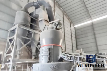
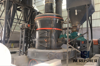
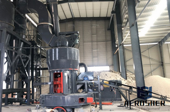
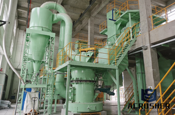
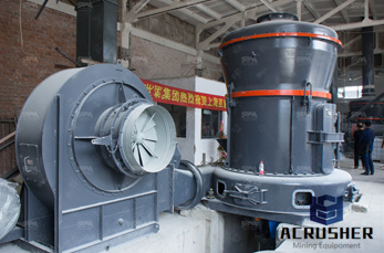
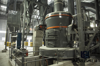
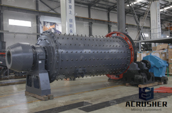
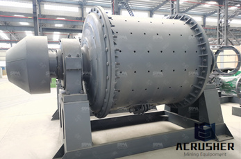
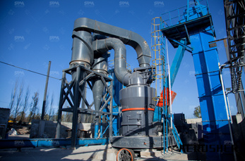
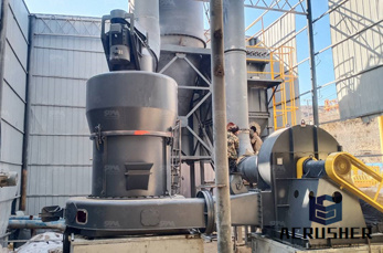
Fly Ash Handling Wherever products are burned it is necessary to have an energy efficient ash handling system, especially in a power station environment where large quantities of pulverized fuel ash (PFA) are ash can be a considerable environmental nuisance as well as being awkward to handle due to its abrasiveness and hydroscopic characteristics.
When the ash storage pond at Tennessee Valley Authority''s (TVA''s) Kingston Fossil Plant in Harriman, Tenn. overflowed into the surrounding areas on Dec. 21, 2008, ash handling processes met ...
Fly Ash Handling System Flow Diagram. Macawber beekays product profile includes vacuum system for extraction of dry fly ash collected at eco air preheater duct electrostatic precipitator hoppers of pf type boilers vacuum system is generally adopted when the extraction distance is less, numbers of esp hoppers are more fly ash handling system macawber beekay.
flow diagram of coal handling plant . 6 · flow diagram of coal handling plant of power plant . flow diagram of coal handling plant of power plant 8956 Ratings ] The Gulin product line, consisting of more than 30 machines, sets the standard for our industry. Get price
Concrete Batching Process Description 15 Concrete is composed essentially of water, cement, sand (fine aggregate) and coarse aggregate. Coarse aggregate may consist of gravel, crushed stone or iron blast furnace slag. Some specialty aggregate products could be either heavyweight aggregate (of barite, magnetite, limonite,
Transforming Bottom Ash . Into Fly Ash in Coal Fired Power Stations . ... The following flowdiagram shows in deta il the bottom ash recycling system adopted for Fiume Santo power plant. Coal Feeders. COAL ... downstream for the MAC system for dry bottom ash handling. Utilizing new pipe
materials handling applications. Additionally this type of system can be utilized in ash removal plants where it is particularly suitable for the removal of fly ash from a baghouse or ESP. The fly ash discharge points are connected to a common FLUIDCON conveying pipe and the ash is continuously removed and can be conveyed long distances.
Fly ash is the fine particles gathered by the fume cleaning system, predominantly the baghouse, and may contain CaCl 2, CaSO 4, Ca(OH) 2, active carbon, and most importantly, dioxins and soluble heavy metals. ... Schematic/flow diagram of an ashhandling plant''s wet bottom ash disposal system.
ash with fly ash for use in the cement industry. The MAC® (Magaldi Ash Cooler) is the latest technology for the dry removal, cooling and conveying of bottom ash from balanced or negative draft, pulverized coal fired boilers. The system does not require any water and utilizes the negative pressure inside the boiler to induce air flow through
INTEGRATED FLY ASH HANDLING SYSTEM: (Schematic flow diagram) Stage I C stn. Fly ash Hoppers Exist. Recip Compr. 30 TPH. Fine Ash. C 1 Existing Silo (Cap:350 T) F stn. Intm. Hopper. Silo (New) 130 ( ''C'' stn) F stn. Fly ash Hoppers. Stage I Centrifugal Compr. Compr. (After rehibilitation) Stage II CentrifugalCo mpr. StageII. 80 TPH. 80 ...
product ash storage domes, and associated equipment for the handling and transferring of fly ash. The STAR Facility is designed to process up to 360,000 tons of fly ash per year, which includes fly ash produced primarily by the Morgantown and Chalk Point generating stations, thereby diverting the fly ash from its current disposal practices.
Overview: Fly ash is the byproduct of pulverized coal that has been injected into the burning zone of a boiler. Upon reaching approximately 1500° C (2700°F), the noncombustible inorganic materials in the coal melt and fuse together as tiny molten droplets.
Doc 04: Fly Ash Handling System Flow Chart SE Unit 2 Doc 05: Fly Ash Handling System Flow Chart SE Units 3 and 4 Doc 06: Fly Ash system Intermediate Storage Doc 07: Miller Plant Water Use Flow Diagram Doc 08: Miller Steam Plant Ash Pond Dam, Biennial Inspection Observations, October 25, 2006 Doc 09: Miller Steam Plant Ash Pond Dam, Dam Safety ...
Low velocity fly ash handling Low velocity Low velocity fly ash handling 1. ... Retrofit of dilutephase ash handling system. handling 8 tons/hour for each system for 260 metres. ... APPENDIX A FLOW DIAGRAMS AND PROCESS DESCRIPTIONS FUEL PREPARATION PROCESSES FROM MUNICIPAL SOLID WASTE Block diagrams or process schematic diagrams of nine ...
WhatsApp)